|
|
|
Who's Online
There currently are 6043 guests online. |
|
Categories
|
|
Information
|
|
Featured Product
|
|
|
 |
|
|
There are currently no product reviews.
 ;
Good quality, all schematics of few of models. There is also short form of user manual and regulation manual.
;
Perfect copy of the service manual. you can enlarge every page, and it comes up
with all details.
;
It´s very very nice manual with all, what i need. Original in good quality. Very fast business. Very much thanks...
;
Purchased the manual that I was looking for at a great price and could download it easily.. Great service experience and for future purchases I plan to use the site.
Thank you very much
;
Exactly what was needed to assess the product - excellent value and great service
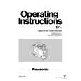
5-9. MIC Base Unit Replacement
(Removal) 1. Remove the Cassette Cover, both Side Panel and Cassette Up Unit, and then open MAIN C.B.A. 2. Disconnect the connector P507 on Servo C.B.A. 3. Unscrew the 2 screws (A) and remove the MIC Base Unit as shown in Figure M15.
5-10. S1 & T1 Post Loading Arm Unit Replacement and Adjustment
(Removal) 1. Remove the Cassette Cover, both Side Panel and Cassette Up Unit, and then open MAIN C.B.A. 2. Remove the Mechanism Chassis Unit and the Drum Unit. 3. Remove the T1 Guide and the Cleaning Arm Unit.
(Installation) 1. Install the new MIC Base Unit according to the reverse procedure for removal. 2. Confirm that the M cassette touches to MIC Base Unit properly.
4. Turn the Emergency Gear to be in middle loading position and unscrew the screw (D),(E) as shown in Figure M16. 5. Remove the S5 Stopper Base and the Tension Arm Unit (Refertoitem14 &15). 6. Unscrew the screw (A) and remove S1 Post from the Loading Rail as shown in Figure M16. 7. Remove the Cut Washer (B) and remove the S1 Loading Arm Unit as shown in Figure M16. 8. Unscrew the screws(C), and then remove the T1 Post from Loading Rail as shown in Figure M16. 9. Remove the T1 Boat Unit from T1 Loading Arm Unit as shown in Figure M16.
(Installation) 1. Install the new S1 or T1 Loading Arm Unit according to the reverse procedures for removal. Then S1 Post Loading Arm Unit Phase Adjustment should be performed. 2. After installing, confirm that the S1 and T1 Post moves smoothly on the Loading Rail. Fig.M15 (Adjustment) 1. Adjust S1 Post Loading Arm Unit so that the hole (A) should match with the hole (B) as shown in Figure M16. 2. When installing the T1 Boat Unit, the hole (A) Should match with the hole (B) as shown in Figure M17. 3. Tension Arm, Post Height Pre-Adjustment and Linearity Adjustment (Refer to the Section 3) should be performed.
MEC-15
|
|
|
> |
|