|
|
|
Who's Online
There currently are 5469 guests online. |
|
Categories
|
|
Information
|
|
Featured Product
|
|
|
 |
|
|
There are currently no product reviews.
 ;
This manual was the factory original. Excellent value and contained all the details I needed. Easy dowwnload provided the information when I needed it.
 ;
Impeccable, document très complet. Perfect, i get all i need. All schematic are correct. Thanks
;
The manual is of better quality compared to other. I found it less expensive and therefore it it is the best buy cost vs quality.
;
I bought the service-manual of the sony ICB-1020(an old transmitter-receiver) at "www.Owners-Manual.com", I found the service-manual for a fairly cheap price(in comparison with other sellers). I filled in some questions, payed the order with Ideal, and within 24 hours I had my service manual. I was very happy:In no time I had my service-manual and everything, but literally everything was noted down in the manual; the electronic scheme, the parts list, etcetera.
A very practical, reference-document.
;
This comprehesive service maual was greatly appreciated, as was the digital download.
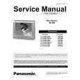
Adjust the Purity rings to set the vertical green raster precisely at the center of the screen (see Fig. 12).
NOTES: 1. CRT warm up with white screen (three guns activated) is needed to stabilize the shadow mask expansion. 2. Initial center static convergence (roughly centers three gun beams) is required in order to perform purity adjustment.
Figure 12. Green Raster Adjustment
Green Raster
Slowly move the deflection yoke forward until the best overall green screen is displayed. Tighten the deflection yoke clamp screw. Press the Recall button on the Remote Control again until the purity check (blue screen) and (red screen) appear and observe that good purity is obtained on each respective field. Press the Recall button on the Remote Control again until Purity check (white screen) appears. Observe the screen for uniform white. If purity has not been achieved, repeat the above procedure.
Align The converged red/blue dots with the green dots at the center of the screen by rotating the R&B&G pole Static Convergence Magnets. Melt wax with soldering iron to reseal the magnets. Slightly tilt vertically and horizontally (do not rotate) the deflection yoke to obtain a good overall convergence. If convergence is not reached at the edges, insert permalloy (see following section) from the DY corners to achieve proper convergence. Recheck for purity and readjust if necessary. After vertical adjustment of the yoke, insert wedge at 11 o�clock position, then make the horizontal tilt adjustment. Secure the deflection yoke by inserting two side wedges at 3 and 7 o�clock positions. Apply adhesive between tab (thin portion) of wedge and CRT and place tape over the tab to secure to the CRT.
Permalloy Convergence Corrector Strip (Part No. 0FMK014ZZ)
This strip is used in some sets to match the yoke and CRT for optimum convergence. If the yoke or CRT is replaced, the strip may not be required. First converge the set without the strip and observe the corners. If correction is needed: 1. Place strip between CRT and yoke, in quadrant needing correction. Slowly move it around for desired results. 2. Press adhesive tightly to the CRT and secure with tape.
Final Convergence Procedure (see Fig. 13
through Fig. 15):
Note: Vertical size and focus adjustments must be completed prior to performing the convergence adjustment. Connect a dot pattern generator to the Receiver. The Brightness level should not be higher than necessary to obtain a clear pattern.
Converge the red and the blue dots at the center of the screen by rotating the R&B pole Static Convergence Magnets.
- 16 -
|
|
|
> |
|