|
|
|
Who's Online
There currently are 5961 guests online. |
|
Categories
|
|
Information
|
|
Featured Product
|
|
|
 |
|
|
There are currently no product reviews.
 ;
It´s very very nice manual with all, what i need. Original in good quality. Very fast business. Very much thanks...
;
Purchased the manual that I was looking for at a great price and could download it easily.. Great service experience and for future purchases I plan to use the site.
Thank you very much
;
Exactly what was needed to assess the product - excellent value and great service
;
A site where discontinualed schematic diagrams and back dated information can be found on discontinued radios tv's and any electronic equipment can be found. Newer manuals either Service and operating manuals. Radio amateurs should find this site a great source for ham radio equipment manuals. I will return to this site should I need information on any electrical equipment. priced easy to download in a PDF format and print pages need to undertake the repair.
;
Quality scan of the original. All the detail necessary to troubleshoot, repair and adjust the unit. I'm sure I will be downloading more manuals in the future as the need arises.
Disassembly for Service
Back Cover
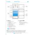
Remove all the screws marked with an arrow( ) from the back of the Receiver. Note: Screw configuration, type, and number of screws vary depending on the model of the Receiver serviced and the application; various models are covered in this Manual. Use same hardware when reassembling the receiver. � 3 screws at the top edge of the Receiver. � 2 screw by the A/V jacks. � 1 screw by the antenna jacks. � 1 screw at each lower corner of the Receiver. � 1 screw by the retainer plate of the AC power cord. � 1 scree by the Flyback assy.
Speakers
Speakers are assembled to the speaker dome with 4 screws. The speaker/Dome assy is secured to the Speaker Bracket (horn) with 2 screws.
A-Board - Main Chassis
The A-Board assembly rest on the cabinet rails as well as the P-Board. Slide chassis out. Disconnect plug connectors; release wire ties and holders as required for complete chassis removal. The A-Board is connected to the P-Board by two connectors: A1, A2 to P1 and P2 in P-Board. To remove either boards, unplug the connectors on the P-Board. Note: Some tie-wraps that secure the wire dressings may need to be unfastened for chassis removal.
Figure 5. Speaker Removal
Keyboard
Keyboard is pushed to the front by the chassis.
Disassembly for CRT Replacement
1. Discharge the CRT as instructed in the Safety Precautions (see page 2). 2. Disconnect the yoke (DY) plug, degaussing coil (DEG) plug and the CRT 2nd anode button from the board. 3. For some models, unplug Geo-magnetic Coil from P-Board, G15. 4. Remove the C-Board from the CRT socket and unplug the black wire (CRT dag ground) C11. 5. Unplug Convergence Yoke CY from C-Board, C2. 6. Lift the Main Chassis (A-Board) and all mounted boards completely out with the CRT Board attached. 7. Disassembly the speakers and speaker brackets from front cabinet.
C-Board - CRT Output
Plugs into the socket on the CRT neck. To release the Focus wire, use a flat tool to release the tab in the socket, pull the wire-look up and remove the wire by pulling away the socket, To re-insert, close the wire-look by pushing until is secured with the tab, and insert the wire into the socket
CRT Replacement
1. Perform Disassembly for CRT Replacement procedure. 2. Insure that the CRT H.V. Anode button is discharged before handling the CRT. Read the Safety Precautions (see page 2) on handling the picture tube. 3. Remove the components from the CRT neck and place the cabinet face down on a soft pad. 4. Note the original order for the CRT mounting hardware as they are remove from the CRT mounting brackets at each corner of the CRT. 5. Remove the CRT with the degaussing coil and the dag ground braid attached.
Figure 4. Focus Wire Removal
-9-
|
|
|
> |
|