|
|
|
Who's Online
There currently are 6043 guests online. |
|
Categories
|
|
Information
|
|
Featured Product
|
|
|
 |
|
|
There are currently no product reviews.
 ;
Great PDF easy to read good info needed for replacment of belts and assembly and specs.
;
complete and unabridged very good quality
easy to download.
recieved in two days.
;
Awesome manual. Complete diagrams of all board assemblies as well as how to get to each part of the t.v. down to the individual screws and their locations. Get it.
;
perfect copy, im very satisfied, i was need the diagram over the powersupply and
the copy was very sharp
;
This is exactly the service manual I needed.
Complete with all schematics, partslists, PCB layouts and alignment instructions.
This manual covers both the T-4970 en T-488F Onkyo tuner.
Disassembly for Service
Back Cover
Remove all the screws marked with an arrow( ) from the back of the Receiver. Note: Screw configuration, type, and number of screws vary depending on the model of the Receiver serviced and the application; various models are covered in this Manual. Use same hardware when reassembling the receiver. � 3 screws at the top edge of the Receiver. � 2 screw by the A/V jacks. � 1 screw by the antenna jacks. � 1 screw at each lower corner of the Receiver. � 1 screw by the retainer plate of the AC power cord. � 1 scree by the Flyback assy.
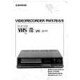
Speakers
Speakers are assembled to the speaker dome with 4 screws. The speaker/Dome assy is secured to the Speaker Bracket (horn) with 2 screws.
A-Board - Main Chassis
The A-Board assembly rest on the cabinet rails as well as the P-Board. Slide chassis out. Disconnect plug connectors; release wire ties and holders as required for complete chassis removal. The A-Board is connected to the P-Board by two connectors: A1, A2 to P1 and P2 in P-Board. To remove either boards, unplug the connectors on the P-Board. Note: Some tie-wraps that secure the wire dressings may need to be unfastened for chassis removal.
Figure 5. Speaker Removal
Keyboard
Keyboard is pushed to the front by the chassis.
Disassembly for CRT Replacement
1. Discharge the CRT as instructed in the Safety Precautions (see page 2). 2. Disconnect the yoke (DY) plug, degaussing coil (DEG) plug and the CRT 2nd anode button from the board. 3. For some models, unplug Geo-magnetic Coil from P-Board, G15. 4. Remove the C-Board from the CRT socket and unplug the black wire (CRT dag ground) C11. 5. Unplug Convergence Yoke CY from C-Board, C2. 6. Lift the Main Chassis (A-Board) and all mounted boards completely out with the CRT Board attached. 7. Disassembly the speakers and speaker brackets from front cabinet.
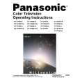
C-Board - CRT Output
Plugs into the socket on the CRT neck. To release the Focus wire, use a flat tool to release the tab in the socket, pull the wire-look up and remove the wire by pulling away the socket, To re-insert, close the wire-look by pushing until is secured with the tab, and insert the wire into the socket
CRT Replacement
1. Perform Disassembly for CRT Replacement procedure. 2. Insure that the CRT H.V. Anode button is discharged before handling the CRT. Read the Safety Precautions (see page 2) on handling the picture tube. 3. Remove the components from the CRT neck and place the cabinet face down on a soft pad. 4. Note the original order for the CRT mounting hardware as they are remove from the CRT mounting brackets at each corner of the CRT. 5. Remove the CRT with the degaussing coil and the dag ground braid attached.
Figure 4. Focus Wire Removal
-9-
|
|
|
> |
|