Please tell us what you think and share your opinions with others. Be sure to focus your comments on the product. You will receive $2.00 of store credit for Your review.
Please tell us what you think and share your opinions with others. Be sure to focus your comments on the product. You will receive $2.00 of store credit for Your review.
Having bought a pre-owned Sony FM stereo tuner through eBay, it came without any manuals. It soon became clear that to get the best from this excellent tuner I needed a decent manual because much of the operation was not intuitive to a newboy to hi fi like me. I managed to download the official Sony multi-lingual manual from Owner-Manuals.com with no problem at all - a really quick and easy service. I'm very glad I did because I found out all the operations of the tuner and was then able to not only set it up quickly but also to get much more from it that poke-and-hope trialling would ever achieve. In my book $4.99 very well spent.
This manual is immaculate in it's accuracy. Everything is written very clearly and easy to understand. Written by a professional who wants to convey a clear and easy to understand message!!
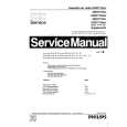
Text excerpt from page 17 (click to view)
YH Adjustment (VR2 for vertical dynamic convergence) 1. Apply a crosshatch pattern. 2. Adjust contrast and brightness customer controls to obtain a correct picture. 3. With a driver Adjust VR2 (located in deflection yoke board Fig. 19) to obtain a proper corvergence at left and right side of the screen. (see Fig. 14)
Permalloy convergence corrector strip (part No. 0FMK014ZZ)
This strip is used in some sets to match the yoke and CRT for optimum convergence. If the yoke or CRT is replaced, the strip may not be required. First converge the set without the strip and observe the corners. If correction is needed: 1. Place strip between CRT and yoke, in quadrant needing correction. Slowly move it around for desired results. 2. Press adhesive tightly to the CRT and secure with tape.
DAF adjustment
Preparation: 1. Apply a crosshatch pattern. 2. Set user controls, bright to center and picture to max. 3. Connect a frequency counter to TPD10. Procedure: 1. Connect channel one of the oscilloscope with 100x1 probe to TPP33 (pin-1 T1551). 2. Connect channel two of the oscilloscope with 10x1 probe to CRT HEATER (L-Board). 3. Adjust �HDAFP� so both waves are in the same position. 4. Adjust �HDAFW� so TPP33 is 1.5 ± 0.5kVpp.
TPP33
G B&R G B&R
G B&R G B&R
Figure 14. VR2 Adjustment (YH)
XV Adjustment (precise adjustment)
1. Apply a crosshatch pattern. 2. Adjust contrast and brightness customer controls to obtain a correct picture. 3. With a driver adjust the coil located in deflection yoke board to obtain a proper convergence horizontally.
B&R G B&R G
HEATER PIN
B&R G B&R G
Figure 16. DAF adjustment
Figure 15. XV adjustment
Note:
Apply a red pattern and confirm purity, if purity is poor, repeat purity adjustments.