|
|
|
Who's Online
There currently are 6043 guests online. |
|
Categories
|
|
Information
|
|
Featured Product
|
|
|
 |
|
|
There are currently no product reviews.
 ;
Great manual just what I needed, great service as always, thanks.
;
Great quality complete service manual! complete parts list and drawings. Thanks!
;
Great quality complete service manual! complete parts list and drawings. Thanks!
;
Very good quality, prompt response. This website has reasonable prices and wide range of manuals that are hard to find.
;
The document was usefull, and it was exactly what I was looking for.
4 CIRCUIT OPERATIONS
4.1.
4.1.1.
FACSIMILE SECTION (for KX-FP80)
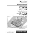
THERMAL HEAD
Please replace original Service Manual page 138 in the KX-FP80. (6.4.3.THERMAL HEAD) 2.Circuit Operation Refer to the block diagram and the timing chart on the following page. There are 9 driver ICs aligned horizontally on the thermal head and each one of these ICs can drive 192 heat-emitting registers. This means that one line is at a density of 192�9=1728 dots=(8 dots/mm). White/Black (white=0, black=1) data in one line increment is synchronized at IC501 pin 115 (THCLK), and sent from IC501 pin 114 (THDAT) to the shift register of the ICs. The shift registers of the 9 ICs are connected in series, and upon the shift of the 1728 dot increment, the shift register becomes filled with data, and a latch pulse is emitted to each IC from IC501 pin 118 (THLAT). With this latch pulse, all the contents of the shift registers are latched to the latch registers. Thereafter, through the addition of strobes from the IC501 pins (105, 106), only the dot location of black (=1) among latched data activates the driver, and the current passes to heat the emitting body to cause heat emission. Here, the two line strobes, STB1 to STB2, impress at intervals of 9.216 msec, as required for one-line printout. The sequence is shown on the next page. [Moreover, for the strobe width, the thermistor value inside the thermal head is detected according to IC501 pin 2. Depending on that value, the strobe width is recorded in ROM (IC502). Accordingly, the strobe width is determined.] When the thermal head is not used, the IC501 (23, THON) becomes low , Q501 turns OFF, IC506 turns OFF, and the +24V power supply for the thermal head driver is not impressed to protect the IC.
12
|
|
|
> |
|