|
|
|
Who's Online
There currently are 5940 guests and
1 member online. |
|
Categories
|
|
Information
|
|
Featured Product
|
|
|
 |
|
|
There are currently no product reviews.
 ;
Scan are good quality and overall just what i was looking for. Thanks!
 ;
Very good quality pdf file, no missing pages and all words and schematics clearly readable. Whole manual is present featuring different languages.
;
Very,very good manual.It was very explicit and readble.It was helpfull.Thanks.
;
The service manual is scanned, but high quality, high resolution. The smallest texts on schematics diagram is readable. Super! Thank you!
;
I am satisfied with the service. And if need another manual, i will definitely buy from this site. Keep up the good work.
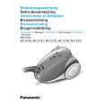
REPLACEMENT OF MAIN PARTS
3. Separate cord reel unit and cord reel support. (Fig. 18) 4. Replace the cord reel unit with a new one. 5. Reassemble cord reel unit and cord reel support and refasten the screw. NOTE: Wind up the power cord extra times as indicated on the spring plate to maintain the cord reel spring efficiency. 6. Connect the lead wires according to the schematic diagram and place the cord reel ass�y into place. Then reassemble the remaining parts in the reverse order.
Cord reel unit Cord reel support
Screw
Fig. 18 (2) Power cord 1. Remove cord reel unit and dissamsenble it as explained previously in paragraph (1) �Cord reel unit�, points 1-3. 2. Unwind the total power cord length from the cord reel. 3. Press and release the stopper on the cord reel and lift the contact base by pushing the lower end. (Fig. 19) 4. Disconnect the power cord from the contact base and replace it with a new one. (Fig. 20) NOTE: Observe the colour of the power cord lead wires before reinstalling the new one. 5. Insert the contact base through the cord reel slot and wind up the total power cord length in the arrow direction as indicated on the spring plate. (Fig. 21) 6. Reassemble cord reel unit and cord reel support and refasten the screw. Then wind up the power cord extra times as indicated on the spring plate to maintain spring efficiency. 7. Place cord reel ass�y into the lower body . Connect the lead wires according to he schematic diagram and reassemble the remaining parts in the reverse order.
Blue wire Stopper
Fig. 19
Brown wire
Contact base
Fig. 20
Fig. 21
15
|
|
|
> |
|