|
|
|
Who's Online
There currently are 6043 guests online. |
|
Categories
|
|
Information
|
|
Featured Product
|
|
|
 |
|
|
There are currently no product reviews.
 ;
Thanks God for the internet and thanks for the service like this - proffessional solution on time.
;
About the service it's very fast and reliable. About the manual the quality is high enough to read even the tiniest details on the wiring diagrams so you can't ask much more than that, let it alone for a manual of a product from 20 years ago. Thank you, very satisfied.
;
The downloaded quality was as good as the orignial
 ;
This is a great and complete Service Manual for the Sharp GF8585HB. Giving full and detailed technical insight. Good to find these manuals online.
;
Everything was ok with the manual. If I have a small complaint, is that I ordered it during the weekend and I think you guys were closed. But I did receive it late Sunday. I will surely order from you again
HOSE REPLACEMENT
Removal
1. Remove the dust cover and dust bag. 2. Remove the end of the hose from the wand. Remove the hose by removing the two screws which secure it to the dust container.
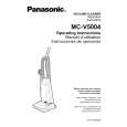
EXPLODED VIEW (NOZZLE HOUSING)�
A BLOCK
A-14 A-3
Replacement
1. Install the new hose by replacing the two screws which secure it to the dust container.
A-1
A-6 A-15
A-7
2. Replace the hose onto the wand. 3. Replace the dust bag and dust cover.
A-2
MOTOR PROTECTOR REPLACEMENT
Removal
1. Remove the dust cover and dust bag. 2. Remove the motor protector (shown in the exploded view in the C Block section), by pushing in, one at a time, on the tabs that secure it to the dust compartment. Push the motor protector out the back of the dust compartment. 3. Once the motor protector is out it can be disassembled for parts replacement.
A-5
Disassembly
1. Holding a pair of needle nose pliers at an angle and in a position where one side of the pliers is against the locking tab, exert enough pressure on the tab to release it (Fig. 11). NOTE: There are two locking tabs present, but only one needs to be released. For reassembly look at the exploded view in the C Block.
A-4
B BLOCK
Installation
(Fig. 11)
1. Reinstall the motor protector into the dust compartment by aligning the two tabs under the top flange with the slots in the dust compartment and applying pressure until it snaps into place.
A-8
A-10 A-11 A-12
A-9
A-13
- 16 -
-5-
|
|
|
> |
|