|
|
|
Who's Online
There currently are 5678 guests online. |
|
Categories
|
|
Information
|
|
Featured Product
|
|
|
 |
|
|
There are currently no product reviews.
 ;
thanks a lot.
without the service manual my handycam was going to the trash.
good job, go on.
bye
 ;
This service manual is a good copy of the original, complete and fully readable. It is really useful to repair my Tv set following its clear instructions.
;
Excellent quality. Easy process to download. No issues or problems at all - was exactly what I was looking for and needed. Great service.
;
I was having a hard time finding the problem with this Mackie 1604 unit. I didn't have a schematic. Went looking on the web and found your site and the price was more then reasonable. Ordered it and within the hour had the manual and within 15 minutes had the unit fixed. Best $4.99 I ever spent. Thank you.
Doug
;
This is a service manual in every sense of the word ( French and German versions of the text are included, as well as English..)
There are explanations of the mechanical and electrical functions, plenty of mechanical drawings, and the needed schematics. The quality of the scanning is excellent - all the component values are clearly legible - and very usefully there are pcb component layouts, so you can find a component on the schematic, and then very quicky pinpoint its physical location on the relevant pcb.
I cannot see how I can give this manual any less than the maximum 5 stars! Great value for money, which will pay for itself immediately. Excellent all round!
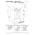
EXPLODED VIEW (GENERAL PARTS)
MOTOR REPLACEMENT
Removal
1. Remove the dust cover by grasping the top near the on-off switch and pulling sharply out toward you. 2. Remove the lower plate, agitator assembly, belt, the plastic shaft, light bulb assembly and the nozzle housing as instructed in the respective removal sections.
Screws Motor Case
A C B
3. Turn the vacuum over to the front side. NOTE: The dust container packing is positioned over the top of the motor case. Pull up on the portion of the dust container packing that lies across the top part of the motor case to free the motor case for removal. 4. Remove the five (5) screws from the motor case and then remove the motor case, (Fig. 16).
(Fig. 16)
5. Disconnect the motor leads and remove the motor. Remove the motor support rubber (rear), noise suppressor, flange and the motor support rubber (front). Place these items on the new motor. See the D Block for a view of these.
Installation
1. Place the motor back into the dust compartment. Align the tabs on the metal flange with the tabs in the dust compartment. 2. Rewire per the Pictorial Diagram. 3. Replace the motor case and the five (5) screws. 4. Replace the dust container packing by inserting it into the groove in the dust container. Use a screwdriver or a quarter to push the packing firmly into the groove. 5. Turn the vacuum back over and replace the plastic shaft, light bulb assembly, nozzle housing, belt, agitator assembly, and lower plate according to the respective installation instructions.
CARBON BRUSH REPLACEMENT
Removal and Installation
1. Complete brush change on one side before starting on the other side. There are two (2) brushes located on the motor as identified by (Fig. 17). Remove the brush assembly by using a Phillips head screwdriver to remove the screw that holds the brush holder onto the motor. See (Fig. 17) for screw location. NOTE: Do not drop screws into the motor. 2. Place new brush assembly on the motor. NOTE: Make sure that the amp terminal on the bottom of the brush assembly is inserted into the receptacle on the motor (Fig. 18). 3. Replace the Phillips screw that was removed. 4. Repeat steps 1-3 for the other brush assembly.
Amp Terminal
Receptacle
Carbon Brushes
D
Brush Screws
(Fig. 17)
(Fig. 18)
-4-
- 17 -
|
|
|
> |
|