|
|
|
Who's Online
There currently are 5835 guests online. |
|
Categories
|
|
Information
|
|
Featured Product
|
|
|
 |
|
|
There are currently no product reviews.
 ;
Once again owner-manual.com has saved the day for me, and come through with the manual I need. I looked other places too, and couldn't find it anywhere. Thank You owner-manual.com!!! You're the BEST!
;
very good quality that can be magnified several times, and it remains readable.
For sure I will return next time the need for a service manual arise.
;
The service manual is really great - thanks to it I was able to install the laser unit and thus "save" my CD-player, which seemed to be impossible before I had the manual.
;
Downloaded the Service manual OK of the Technics Piano and have now repaired it and its going fine. Excellant; thank you for the fine servce. A.M
 ;
This site is working fine! Did buy a manual for SX-EX25L and after a while I could download it and fix the problem. Nice and easy!
Disassembly for Service
Note:
Board ground wires may have to be disconnected to disassemble some boards. All ground wires must be reconnected using jumper leads, if necessary, before power is applied to PTV for service. 2. Remove (3) screws from around the A/V terminal board (marked with arrows).
Speaker Grille Removal
(Figure 8.) 1. The 2 Speaker Grilles are secured to the wooden base of PTV. Grip each panel from the sides and botton part, gently pull forward to remove. When reassembling, make certain to firmly press on the panel where the insertion points (4) are located, one on each corner. 2. The Center Front Cover is secured by 4 screws.
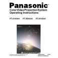
Panasonic
Front Cover
Figure 9. Lower Cabinet Back Removal
Cabinet Back Cover Removal
(Figure 10) 1. First remove the Cabinet Back Lower Cover. 2. The top back cover is secured with (16) screws around its perimeter (See Figure 10 for screws location). 3. Be careful not to damage the mirror attached to the underside of cover.
Speaker Grill
Figure 8. Speaker Grill Removal.
Keyboard Removal (7-Key Button)
(Figure 8) 1. Remove the Speaker Grill. (see Figure 8) 2. Unplug the cables (2) from the Keyboard assembly. Remove the 2 screws from the left and right sides of Keyboard assembly. Tilt the Keyboard assembly upward and release it from the screen frame assembly.
Speakers Replacement
1. Remove the speakers grill. (see Figure 8) 2. Each speaker set is secured to the cabinet with (4) screws. 3. Disconnect the R & L speaker lead connectors from the speaker units.
Cabinet Back Lower Removal
(Figure 9) 1. Remove (7) hex screws around its perimeter marked with arrows. (See Figure 9 for screw location).
Figure 10. Cabinet Back Cover Removal
- 11 -
Service Manual
|
|
|
> |
|