|
|
|
Who's Online
There currently are 6043 guests online. |
|
Categories
|
|
Information
|
|
Featured Product
|
|
|
 |
|
|
There are currently no product reviews.
 ;
Very quality copy of original service manual, which contains the circuit diagrams, PCB and lists of components, well as recommendation for calibration procedures of device, also everything else, that need for repair, tuning and use this oscilloscope.
All presented copies have high-resolution, so you can view all in detail.
This manual will very useful for simple owners and for repairers.
I recommend these manual, because myself is owner of Philips PM3216 and I need sometimes servicing these oscilloscope (principally calibrating).
Also, these document is an example of excellent design of technical documentation.
;
Excellent printing quality.
A complete and very usefull service manual with all details.
GREAT SERVICE AT VERY LOW PRICE!
A+++++++++++++++++++++++++
 ;
manual excelente completo , diagramas y esquemas bien presentados y buena calidad de imagen.
;
muy buen manual completo de buena calidad de impresion preciso y detallado , muy útil para la reparación.
;
The service manual is a good quality scan of the Panasonic NV-850, which is electrically identical to the Philips VR 6920, but mecanically just nearly.
Rear support plate removal
3. Remove four screws as shown. Two behind the metal sheet, one between ballast and fan, and one under the ballast.
Lamp Connector
8. The optical block is shown below.
Optical block screw location
4. Unplug L1 connector. 5. Open the front SD card door before to take optical block out, to avoid door from getting stock 6. Lift the upper cabinet, then take the optical block out by pulling out, up and out as shown. NOTE: Do not take out the optical block completely, there is the lamp connector behind that must be unplugged.
10.2. L-Board Removal
1. Remove the three screws that holds the board.
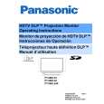
Optical block pull out
7. Unplug the lamp connector shown inside the white circle. Then take the optical block out completely.
2. When placing this board, do not tight completely the three screws shown on above picture, first move the board right/left and up/down to center the image on the screen, then when best overall image centering is obtained, tight the screws. NOTE: Position of L-Board is critical to the raster position. If the black screws are not removed, the L-Board will keep its position. However, if they are removed, raster position must 18
|
|
|
> |
|