|
|
|
Who's Online
There currently are 5930 guests online. |
|
Categories
|
|
Information
|
|
Featured Product
|
|
|
 |
|
|
There are currently no product reviews.
 ;
Excellent printing quality.
A complete and very usefull service manual with all details.
GREAT SERVICE AT VERY LOW PRICE!
A+++++++++++++++++++++++++
;
Excellent printing quality.
A complete and very usefull service manual with all details.
GREAT SERVICE AT VERY LOW PRICE!
A+++++++++++++++++++++++++
;
Pioneer CDXP23S is an old model and has been top useful for me to find this Manual. CD Player is still repaired.
;
Inventory (Stock): a rather extensive list of service manuals, which are hard to find, especially 15+ yrs old.
Pricing: very reasonable.
Delivery/Response: Very Prompt delivery of product: Placed order and received download access within 1.5hrs.
Service Manual: a rather complete OEM service manual (15.5MB pdf file size). Scan quality was very good, accept for a few circuit board diagrams that were dark; Zooming, however, clarified the image. Has the required information for servicing the LD Player.
;
Perfect copy of a necessary document and my Sonic Modulator is repaired!
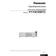
PT-FW100NTU / PT-FW100NTE / PT-FW100NTEA
7.11. Removal of S1-P.C.Board 7.8. Removal of L-P.C.Board
1. Remove the upper case according to the section 7.2. "Removal of Upper Case". 2. Open the front door. 3. Unscrew the 1 screw and remove the front cover (inside). 4. Unscrew the 1 screw and remove the grounding terminal. 5. Unscrew the 2 screws and remove the power separation wall. 6. Remove the front cover. Note: · S1-P.C.Board and S2-P.C.Board are attached. · Remove the front cover after shifting the projection lens upward. 1. Remove the block of Analysis Block, LCD Block and Projection Lens according to the steps 1 through 8 in the section 7.17. "Removal of Analysis Block and Projection Lens". 2. Unscrew the 1 screw and remove the L-P.C.Board.
7.9.
Removal of PI-P.C.Board
1. Remove the ARF drive unit according to the section 7.27. "Removal of ARF Drive Unit". 2. Unscrew the 1 screw and remove the PI-P.C.Board.
7. Disconnect the connector between S1-P.C.Board and S2P.C.Board. 8. Unscrew the 5 screws and remove the S1-P.C.Board.
7.10. Removal of R-P.C.Board
1. Remove the upper case according to the section 7.2. "Removal of Upper Case". 2. Disconnect the connector (S4 or A27) between RP.C.Board and A-P.C.Board. 3. Unscrew the 1 screw and remove the R-P.C.Board.
7.12. Removal of S2-P.C.Board
1. Remove the front cover according to the steps 1 through 6
16
|
|
|
> |
|