|
|
|
Who's Online
There currently are 5923 guests online. |
|
Categories
|
|
Information
|
|
Featured Product
|
|
|
 |
|
|
There are currently no product reviews.
 ;
Very good quality, prompt response. This website has reasonable prices and wide range of manuals that are hard to find.
;
The document was usefull, and it was exactly what I was looking for.
;
OK?..manual is complet and helpfull... for repairing such a old and rare boombox like JVC PCM it is necessary...
;
Super Anleitung. Ordentliche Auflösung. Das ganze noch in Deutsch wäre zu schön. Alle Datenblätter sind sauber Kopiert und alle Leitungswege sind sauber ausgeführt
;
Thanks God for the internet and thanks for the service like this - proffessional solution on time.
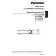
PT-LB20NTU / PT-LB20NTE / PT-LB20NTEA / PT-LB20U / PT-LB20E / PT-LB20EA / PT-LB20SU / PT-LB20SE / PT-LB20SEA / PT-LB20VU / PT-LB20VE / PT-LB20VEA
7.4.
Removal of WL-P.C.Board (PTLB20NTU/E/EA only)
1. Remove the upper case according to the section 7.2. "Removal of Upper Case". 2. Unscrew the 4 screws and remove the shield cover and wireless LAN module. Notes: · Because the wireless LAN module is connected with the WL-P.C.Board, work carefully when removing it. · When installing/detaching the antenna connector, insert or pull out it straight along the center of the connector pin. It causes damage and/or poor contacting of the connector when forcibly installing/detaching it. · Connect the connector from the antenna with the original position (connector on the wireless LAN module) after reassembling. 3. Unscrew the 1 screw and remove the WL-P.C.Board.
7.6.
Removal of S2-P.C.Board
1. Remove the S2-P.C.Board block according to the section 7.3. "Removal of A-P.C.Board". 2. Remove the holder while expanding the resin hooks outside. Note: · Work carefully not to damage the resin hook.
7.7.
Removal of K-P.C.Board
1. Remove the analysis block, LCD block and lens according to the steps 1 through 3 in the section 7.11. "Removal of Analysis Block and Lens". 2. For PT-LB20NTU/E/EA, unscrew the 4 screws and remove the shield cover and wireless LAN module.
7.5.
Removal of S1-P.C.Board
1. Remove the upper case according to the section 7.2. "Removal of Upper Case". 2. Remove the water-guide plate.
Notes: · Because the wireless LAN module is connected with the WL-P.C.Board, work carefully when removing it. · When installing/detaching the antenna connector, insert or pull out it straight along the center of the connector pin. It causes damage and/or poor contacting of the connector when forcibly installing/detaching it. · Connect the connector from the antenna with the original position (connector on the wireless LAN module) after reassembling. 3. For PT-LB20NTU/E/EA, unscrew the 2 screws and remove the WL-P.C.Board (with metal fittings for securing WL).
3. Unscrew the 2 screws and remove the S1-P.C.Board.
17
|
|
|
> |
|