|
|
|
Who's Online
There currently are 5802 guests online. |
|
Categories
|
|
Information
|
|
Featured Product
|
|
|
 |
|
|
There are currently no product reviews.
 ;
I was very glad recieving the service manal from You. Additionaly very fast. Extremaly nice servicing. Thanks very mach! Now my GX-220 working better, than it was made. Alexander from Moscow, Russia/
;
Sweet! I won the item on eBay and couldn't adjust the geometry or even keep a steady picure. This guide has the full schematics (not available anywhere else as far as I could tell), and was a bargain for the wealth of knowledge it contains. I hooked it up to my testing equipment, tweaked a few potentiometers and got it playing videogames in no time. Thanks!
;
It was just what I need to fix my old BMW's CD player. Very convenient also. Thank you.
;
Great Manual! It contains all the wiring schematics and mechanical exploded views that are essential for service and repair. I was surprised I even found this for such an old machine. Only wish I knew of this site many years ago.
;
Great manual very clear copied. You are making an incredible job. I appreciate a lot the rapidity and your efficiency. Thanks a lot
5. A/C HEAD HORIZONTAL POSITION ADJUSTMENT
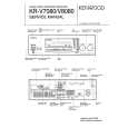
Purpose: To adjust the Horizontal Position of the A/C Head. Symptom of Misadjustment: If the Horizontal Position of the A/C Head is not properly adjusted, a maximum envelope cannot be obtained at the Neutral Position of the Tracking Control Circuit. Place a jumper between TP6003 on the Video Signal Process Section and +5V(TP6009) on the System Control Section of the Main C.B.A. to defeat Auto Tracking. 1. Eject the tape and insert it again to access the Neutral Tracking position. Connect the oscilloscope to TP3002 on the Video Signal Process Section of the Main C.B.A. Use TP6205 as a trigger. 2. Play back the alignment tape and confirm that the RF envelope appears. 3. If adjustment is required, loosen the Black Screw (D) and tighten it lightly. Set the H-Position Adjustment Driver into the Hole (A). Then slowly turn the fixture either clockwise or counterclockwise so that the envelope is at maximum. 4. Before finding the center of the maximum period of the envelope, rotate the fixture back and forth slightly to confirm the limits on either side of the maximum period. 5. Push the Tracking Control Up Button (on the Remote Control) several times (count the number of times pushed) until the maximum envelope is reduced to 1/2. 6. Reset the tracking to the neutral position by ejecting the tape and reinserting it. Push the Tracking Control Down Button (on the Remote Control) several times (count the number of times pushed) until the maximum envelope is reduced to 1/2. 7. If the number of pushing is not the same, then loosen the Black Screw (D) and set the H-Position Adjustment Driver into the Hole (A) to find the center point. Then repeat the above procedure to determine the center point. 8. Tighten Black Screw (D). 9. Remove the jumper between TP6003 and +5V(TP6009).
Black Screw (D)
Hole (A)
Fig. M11 Note: Old type of H-Position Adjustment Driver (VFK0136) can be used for this adjustment.
2-23
|
|
|
> |
|