|
|
|
Who's Online
There currently are 5276 guests online. |
|
Categories
|
|
Information
|
|
Featured Product
|
|
|
 |
|
|
There are currently no product reviews.
 ;
This is a very good quality print (scan) of the original SONY service manual. The original from Sony is on very thin paper. Nevertheless it is very clear and sharp and excellent readable. I'm very satisfied to have now this rare document. I've looking for it many years (infrequent). It contains very detailed circuit diagrams, exploded views, part lists, PCB view with good readable connection lines. Very recommended.
;
A complete manual with all the needed details of calibrations and service instructions about the radio receiver.
A big deal.
Many thanks !
;
Fast delivery and good quality copy. To be recommended
;
Excellent product, very clear print. Detailed circuit and assembly diagrams - this enabled me to repair my CD player with confidence. I highly recommend this site.
;
Fast access, 100% correct and complete service manual
PV-DF205 / PV-DF2035 / PV-DF275 / PV-DF2735 / PV-DF2035-K / PV-DF2735-K
1 SAFETY PRECAUTIONS
1.1. GENERAL GUIDELINES
1. IMPORTANT SAFETY NOTICE There are special components used in this equipment which are important for safety. These parts are marked by in the Schematic Diagrams, Circuit Board Layout, Exploded Views and Replacement Parts List. It is essential that these critical parts should be replaced with manufacturer�s specified parts to prevent X-RADIATION, shock, fire, or other hazards. Do not modify the original design without permission of manufacturer. 2. An Isolation Transformer should always be used during the servicing of Combination DVD VCR whose chassis is not isolated from the AC power line. Use a transformer of adequate power rating as this protects the technician from accidents resulting in personal injury from electrical shocks. It will also protect Combination DVD VCR from being damaged by accidental shorting that may occur during servicing. 3. When servicing, observe the original lead dress, especially the lead dress in the high voltage circuits. If a short circuit is found, replace all parts which have been overheated or damaged by the short circuit. 4. After servicing, see to it that all the protective devices such as insulation barriers, insulation papers, shield, and isolation R-C combinations are properly installed. 5. Before turning the receiver on, measure the resistance between B+ line and chassis ground. Connect (-) side of an ohmmeter to the B+ lines, and (+) side to chassis ground. Each line should have more resistance than specified, as follows : B+ Line 130 V 28 V 220 V Minimum Resistance 110 � (Cold chassis ground) 180 � (Cold chassis ground) 1 k� (Cold chassis ground)
1.2.
LEAKAGE CURRENT COLD CHECK
1. Unplug the AC cord and connect a jumper between the two prongs on the plug. 2. For physically operated power switches, turn power on. Otherwise skip step 2. 3. Measure the resistance value, with an ohmmeter, between the jumpered AC plug and each exposed metallic cabinet part on the receiver, such as screwheads, connectors, etc. When the exposed metallic part has a return path to the chassis, the reading should be between 1 M� and 12 M�. When the exposed metal does not have a return path to the chassis, the reading must be infinity.
1.3.
LEAKAGE CURRENT HOT CHECK
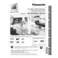
1. Plug the AC cord directly into the AC outlet. Do not use a isolation transformer for this check. 2. Connect a 1.5 k�, 10 W resistor, in parallel with a 0.15 µF capacitor, between each exposed metallic part on the set and a good earth ground, as shown in Figure 1. 3. Use an AC voltmeter, with 1 k�/V or more sensitivity, to measure the potential across the resistor. 4. Check each exposed metallic part, and measure the voltage at each point. 5. Reverse the AC plug in the AC outlet and repeat each of the above measurements. 6. The potential at any point should not exceed 0.75 V RMS. A leakage current tester (Simpson Model 229 equivalent) may be used to make the hot checks. Leakage current must not exceed 1/2 mA. In case a measurement is outside of the limits specified, there is a possibility of shock hazard, and the receiver should be repaired and rechecked before it is returned to the customer.
6. When the TV set is not used for a long period of time, unplug the power cord from the AC outlet. 7. Potentials, as high as 33.0 kV (For model with 20 inch CRT), 33.0 kV (For model with 27 inch CRT) are present when this TV set is in operation. Operation of the TV set without the rear cover involves the danger of a shock hazard from the TV set power supply. Servicing should not be attempted by anyone who is not thoroughly familiar with the precautions necessary when working on high voltage equipment. Always discharge the anode of the picture tube to the CRT ground of receiver before handling the tube. 8. After servicing make the following leakage current checks to prevent the customer from being exposed to shock hazards.
Figure 1
3
|
|
|
> |
|