|
|
|
Who's Online
There currently are 5574 guests and
2 members online. |
|
Categories
|
|
Information
|
|
Featured Product
|
|
|
 |
|
|
There are currently no product reviews.
 ;
Very Good! All the diagram are easy to read, and its complete.
;
This was an excellent source of detailed assembly information on a device which is at least 12 years old. A very lucky find, coupled with great service.
;
Excellent Service Manual and best price on the Internet. This Service Manual covers everything you could ever need including full circuit schematics, component layout diagrams, stripdown procedure and full parts list/breakdown. I needed this to carry out a modification to one of these headunits and this manual covered everything I needed. Fast delivery, processed within a few hours.
 ;
Thought I would never find a copy of the Technics SX-EN2 Service Manual until I found Owner-Manuals.com. Price was very fair and I received the download promptly. While a photocopy, it is quite readable and includes all the pertinent information and diagrams. Thank you Owner-Manuals!
;
I really like this manual and it's reliable.I found and bought easly.thank you.
PV-GS29P / PV-GS36P / PV-GS39P / PV-GS59P / PV-GS29PC / PV-GS39PC / PV-GS59PC
9. Removal of Cassette Cover Unit 1) Remove the 3 Screws (519). 2) Disconnect the F.P.C. from Connector FP7001. 3) Pull off the Mechanism Ass'y & Main P.C.B.
519
Replacement of Mechanism Chassis Ass'y When replacing the Main Chassis Ass'y or the Cylinder Unit, be sure to perform the Envelope Output Adjustment. Refer to "ENVELOPE OUTPUT ADJUSTMENT" in MECHANICAL ADJUSTMENT. Mechanism Chassis Ass'y Handling Caution When servicing the Mechanism Chassis Ass'y without the Cassette Up Unit, do not handle the Sub Chassis of the Mechanism Chassis Ass'y.
Mechanism Chassis Ass'y (without Cassette Up Unit) Sub Chassis
Cassette Cover Unit
519
FP7001
519
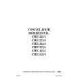
Fig. D10 10. Installation of Main P.C.B. Take care not to damage the F.P.C.s. 1) Connect the F.P.C.s to the connectors on the Main P.C.B., verifying that the direction of the Flexible Cables is correct. Refer to "REMOVAL/INSTALLATION OF F.P.C. FROM NON ZIF (Zero Insertion Force) CONNECTOR." 2) Tighten the 2 Screws (545). 3) After installing the Main P.C.B, confirm the F.P.C.s are positioned as shown.
Sub Chassis
Main P.C.B.
545
Sub Chassis
<Side View> Fig. D11-2
545
Mechanism Chassis Ass'y
Capstan Sub Mechanism Cylinder Head F.P.C. F.P.C. F.P.C. Mechanism Amp F.P.C. F.P.C.
57
|
|
|
> |
|