This document is just what I was looking for, it´s very useful, it contains adjustment procedures for the final stage of the power amp and also
has a complete wiring diagram and description of the main semiconductors used in the design.
Text excerpt from page 16 (click to view)
SA-PM21PC
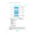
Step 2 : Detach the connector CN803A, CN808A. Step 3 : Detach the connector CP800. Step 4 : Remove the Main P.C.B as arrow shown. Step 1 : Detach the connector CN805A and remove the tuner pack as arrow shown.
10.11. Disassembly of Power P.C.B
· Follow the (Step 1) - (Step 6) of Item 10.2. · Follow the (Step 1) - (Step 4) of Item 10.3. · Follow the (Step 1) - (Step 2) of Item 10.8.
10.10. Disassembly of Main P.C.B
· Follow the (Step 1) - (Step 6) of Item 10.2. · Follow the (Step 1) - (Step 4) of Item 10.3. · Follow the (Step 1) - (Step 4) of Item 10.6. · Follow the (Step 1) - (Step 2) of Item 10.8.
Step 1 : Detach the connector CN505B. Step 1 : Detach the FFC CN801.