|
|
|
Who's Online
There currently are 5550 guests online. |
|
Categories
|
|
Information
|
|
Featured Product
|
|
|
 |
|
|
There are currently no product reviews.
 ;
This is the original manufacturers service manual, with detailed info on the circit boards, explosion drawings of all parts in assembly order, and tuning instructions. The only thing missing is the information on the dimensions of the various drive belts. mail me if you need them. gcrossman_at_aol.com
;
Ordered service manuel for a hard to find plasma tv - your company made it easy to find and purchase - I will use you again
Thanks for your help
 ;
This is a high quality manual with clear schematic and components layout diagrams ; with service procedure included.
;
This service manual for the Kenwood KT-990D was reproduced really well ,is very legible and manual is complete.Combined with the low price paid,in the future,I will be checking Owner-Manuals.com any time I need a manual.
;
When I purchased this manual I had my doubts regarding the quality as the price was so reasonable as compared to other outlets.
The manual itself is of high standard the print is very clear as are the diagrams. Obviously with the diagrams one has to zoom in otherwise it is to small to be able to read.
Overall I am very pleased with the company who delivered as they said and with the manual they supplied.
I occasionally require a manual and now having registered with this company I shall order from them in the future.
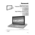
TH-37PHD8GK / TH-37PHD8GS / TH-37PHD8UK / TH-42PHD8GK / TH-42PHD8GS / TH-42PHD8UK
15. Disconnect the couplers(SC45, SC46). 16. Remove the each 2 screws and then slide the SU-Board and the SD-Board to the left.
20. Disconnect the coupler(SS23). 21. Remove the Flexible Cable from the coupler(SS55). 22. Remove the 2 screws and then remove the SS2-Board . 23. Disconnect the coupler(SS22). 24. Remove the Flexible Cable from the coupler(SS56). 25. Remove the 2 screws and then remove the SS3-Board. 26. Disconnect the couplers(SS24, SS32, SS34). 27. Remove the Flexible Cable from the couplers(SS52, SS53). 28. Remove the 6 screws and then remove the SS-Board.
17. Remove the Flexible Cable from the couplers(SU1, SU2, SU3, SU4) and then remove the SU-Board. 18. Remove the Flexible Cable from the couplers(SD1, SD2, SD3, SD4) and then remove the SD-Board.
29. Disconnect the coupler(C12). 30. Remove the 8 screws and then remove the Flexible Cable from the couplers(CA1, CA2, CA3, CA4). 31. Remove the 3 screws and then remove the C1-Board.
19. Remove the 6 screws and then remove the SC-Board.
32. Remove the 8 screws and then remove the Flexible Cable from the couplers(CA5, CA6, CA7, CA8). 33. Remove the 3 screws and then remove the C2-Board.
31
|
|
|
> |
|