|
|
|
Who's Online
There currently are 5584 guests online. |
|
Categories
|
|
Information
|
|
Featured Product
|
|
|
 |
|
|
There are currently no product reviews.
 ;
The manual for Sony LBT-D505 component stereo system is was excellent , with schematics, parts layout and parts list as well as instructions for adjustments for each component. Print was clear even when enlarged.
;
It's exactly a complete and very useful manual with all details what I needed. Thank you!I will come back whenever I need your manuals or schematics.
;
I searched EVERYWHERE looking for the manual/s on this "extinct" amp. Owner-Manuals.com made it available and for nearly nothing. Thanx to them, I can decipher the unknown cables and sort them out. Thanx, Owner-Manuals.com!!
;
Yes thank you i got the file i was after. There was a slight problem in my communication but it all worked out well.
A job well done.
 ;
Great manual...really saved me. The only problem is that I thought I would be able to download it directly when I paid for it but never received the download instructions until the next morning. The board trace pages were somewhat light also: really need to turn up the contrast on the printer before printing them. The schematic page was great; very clear! Well worth the money.
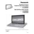
TH-37PHD8GK / TH-37PHD8GS / TH-37PHD8UK / TH-42PHD8GK / TH-42PHD8GS / TH-42PHD8UK
15. Disconnect the couplers(SC45, SC46). 16. Remove the each 2 screws and then slide the SU-Board and the SD-Board to the left.
20. Disconnect the coupler(SS23). 21. Remove the Flexible Cable from the coupler(SS55). 22. Remove the 2 screws and then remove the SS2-Board . 23. Disconnect the coupler(SS22). 24. Remove the Flexible Cable from the coupler(SS56). 25. Remove the 2 screws and then remove the SS3-Board. 26. Disconnect the couplers(SS24, SS32, SS34). 27. Remove the Flexible Cable from the couplers(SS52, SS53). 28. Remove the 6 screws and then remove the SS-Board.
17. Remove the Flexible Cable from the couplers(SU1, SU2, SU3, SU4) and then remove the SU-Board. 18. Remove the Flexible Cable from the couplers(SD1, SD2, SD3, SD4) and then remove the SD-Board.
29. Disconnect the coupler(C12). 30. Remove the 8 screws and then remove the Flexible Cable from the couplers(CA1, CA2, CA3, CA4). 31. Remove the 3 screws and then remove the C1-Board.
19. Remove the 6 screws and then remove the SC-Board.
32. Remove the 8 screws and then remove the Flexible Cable from the couplers(CA5, CA6, CA7, CA8). 33. Remove the 3 screws and then remove the C2-Board.
31
|
|
|
> |
|