|
|
|
Who's Online
There currently are 6043 guests online. |
|
Categories
|
|
Information
|
|
Featured Product
|
|
|
 |
|
|
There are currently no product reviews.
 ;
This service manual of the old video cassette recorder VT-LC50EM is very good readable even the tiniest numbers (i.e. IC-pins). The circuits are very clear. Many details of the schematic are very good described but in GERMAN language. Many schematic details - but complete at all. Common background information of several details are enclosed and physical knowledge of the TFT liquid crystal display for example. The manual lacks PCB drawings. If you understand german I would recommend this manual for you.
;
Hi, this is a very clear manual, nice copy, not quite up to the standard of the very best available but better than many others. I think the price was especially fair for a hard to find manual and I would certainly use this manual seller again. Recommended.
 ;
This schema available for me in good condition. I would highly recommend.
;
Thanks for this "hard to find" service manual.
I apreciate the good quality of scanning and the pages scanned in A3 format.
;
Helpd me mont a new carradio when prewius mont was a mess.
8 Execute Program Number 042 Press the Camera
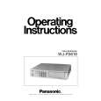
8 Adjust VR35 so that the Burst signal level becomes 300 ±
Selection Button/Preset Position Button 4, 2 and 16 sequentially, the Menu as shown in Table 4-4 will be displayed.
SELF CHECK
14 mV as shown in Fig. 4-6.
8 Confirm that the Sync signal level becomes 300 ± 30 mV
as shown in Fig. 4-6.
700 ± 14 mV 300 ± 14 mV 300 ± 30 mV 042 H PHASE(R-2) 00-0F 0C
Table 4-4 8 Connect the terminated Oscilloscope with 75� to the Recording Output Connector on the Rear Panel. 8 Adjust VR18 so that the Border signal level becomes 700 ± 14 mV as shown in Fig. 4-5. 8 Adjust VR36 so that the Burst signal level becomes 300 ± 14 mV as shown in Fig. 4-5.
8 Confirm that the Sync signal level becomes 300 ± 30 mV 8 Press the Reset Button.
Fig 4-6
(7). Y Pedestal, Y Gain, Chroma Gain and Chroma Phase Adjustment
Test Point: Adjust: Recording Output Connector VR25 (Y GAIN-0) VR26 (Y GAIN-1) VR27 (Y GAIN-2) VR28 (Y GAIN-3) VR29 (Y GAIN-4) VR30 (Y GAIN-5) VR31 (Y GAIN-6) VR32 (Y GAIN-7) VR33 (VBS Y GAIN) VR22 (Y/C Y GAIN) Rear Panel Switch Board Switch Board Switch Board Switch Board Switch Board Switch Board Switch Board Switch Board Switch Board Switch Board Switch Board Switch Board Switch Board Switch Board Switch Board Switch Board Switch Board Switch Board Switch Board
as shown in Fig. 4-5.
700 ± 14 mV 300 ± 14 mV 300 ± 30 mV
Fig 4-5
8 Press the Reset Button. 8 Change the connection of the terminated Oscilloscope
VR23 (Y/C C GAIN) VR2 (C PHASE-0) VR4 (C PHASE-1) VR6 (C PHASE-2) VR8 (C PHASE-3) VR9 (C PHASE-4) VR12 (C PHASE-5) VR14 (C PHASE-6) VR16 (C PHASE-7)
with 75� to the Multiscreen Output Connector on the Rear Panel.
8 Execute Program Number 044 Press the Camera
Selection Button/Preset Position Button 4, 4 and 16 sequentially, the Menu as shown in Table 4-5 will be displayed.
SELF CHECK
VR34 (C PHASE) Switch Board 8 Supply the Ramp signal to the Camera Input Connectors 1, PLAY-IN Connector and S-Video Connector of the Playback Input Connector on the Rear Panel. Note : The supplied signals to the Camera Input Connector 1 and S-Video Connector must be synchronized.
8 Connect the terminated Oscilloscope with 75� to the
044
H PHASE(M-2)
00-0F
0C
Table 4-5 8 Adjust VR20 so that the Border signal level becomes 700 ± 14 mV as shown in Fig. 4-6.
Recording Output Connector on the Rear Panel.
24
|
|
|
> |
|