Excellent product and service. I bought a second-hand Casio CPS-60 keyboard which had no manual. Packed full of features which I had no idea how to operate . . .
Google search found this site (and others with the same manual for sale for $8.99!)
I bought the manual and within an hour the download was available. Quality of the scanned images is good - very clear - and the PDF has been created with the pages in the correct order.
I would definitely use this site again.
The manual was everything that I wanted. Clearly printed and delivered in very quick time. Would certainly use again if I needed a manual in the future
Text excerpt from page 3 (click to view)
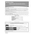
Board Mounting Procedure
The following example is the procedure to mount a network board into the OUT X-1 slot of WJ-SX650 Series. Notes: � This network board can be inserted into the OUT X-1 slot only. � Before the procedure, power off WJ-SX650 Series. � Remove the screws and fixing brackets surely when dismounting. � Fix the screws surely when mounting. � Do not hit the boards against the chassis of WJ-SX650 Series.
Video Video Outp Outp
4. Mount the network board into the OUT X-1 slot, and fix the board with the supplied screws.
SIGNAL
GND
SIGNA
TERM.O MODE MODE N
L
GND
3 DATA 4 NL7 DATA HDR3/TMNL3 1/TM 4/TMNL8 2 HDR NL4 HDR ut Board 2/TM 1 HDR ut Board
TERM.O
FF ON
2 DATA L6 TMN L2 TMN
TMNL1/PS
1 DATA L5 TMN DATA
1. Remove the front panel by loosening the screws.
Network board
5. Mount the video output main board by hooking the board stoppers on the board stopper angles at the front side, by pushing down the board stoppers, and by fixing the screws. Then, attach the front panel.
OPER ATE
Matrix
Switc
her WJ-
SX
650
2. Dismount the video output main board from the front side.
Board stopper angle Board stopper Hook the board stoppers on the board stopper angles, and push down the board stoppers.
Fixing brackets (x4) Screws (x8) � Mount the main board into the slot. � Fix the board with the screws (x3). � Attach the fixing brackets (x4) with the screws (x8). Video output main board Fixing brackets (x4) Screws (x8)
Note: When mounting, insert the main board surely into slits.
3. Dismount the OUT X-1 board from the rear side.
SIGNAL
GND
SIGNAL
GND
FF ON TERM.O
N TERM.O MODE
DATA DATA 3 DATA 4 L7 DATA HDR3/TMNL3 L8 HDR4/TMN HDR1/TMN 2 L4 t Board /TMN 1 HDR2 t Board TMNL TMNL 2 6 2